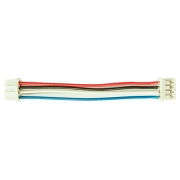
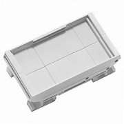
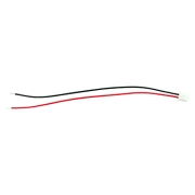
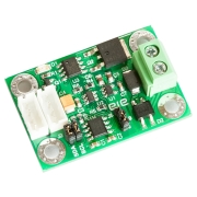
*The RoHS icon on this product indicates that the PCBs, components, solder, and chemicals are all lead-free and RoHS compliant. Additionally, this product is produced using a lead-free process. Unfortunately, we are currently unable to provide documentation confirming that this product is RoHS compliant.
Resources:
*If your browser cannot display the PDF file properly, please save it to your computer and open it with a PDF reader.
Package Includes:
Notes:
- This package does not include Din-Rail PCB holders and cables.
- This board uses 4-pin connectors for I2C bus.
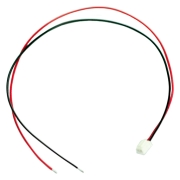
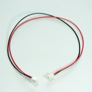
- Side by side linking of this products uses 2.5 inch long of wires.
Features:
- 4 channels of analog inputs
- Input voltage ranges: 0-5V, 0-10V
- Input current ranges: 0-20mA, 4-20mA, 0-40mA
- MCP3424, 12,14,16 and 18-bit ADC, MCP3424
- I2C bus speed 100Khz, 400Khz, 3.4Mhz
- On-board pull-up resistors for I2C bus
- Up to 8 boards on a single bus
- Operating voltage: 2.7V to 5.5V
- Inverse polarity protection circuit for power supply
- 30V over-voltage protections for each input channel
- Input transient suppression for each input channel
- Supports Din-rail PCB holder
This is an analog-to-digital converter board that communicates through the I2C bus, also known as the I2C ADC board. The board features 4 analog inputs. Each input can be connected to either a voltage or current source (but not both simultaneously). It supports the following input ranges:
Voltage: 0-5VDC, 0-10VDC
Current: 0-20mA, 4-20mA, 0-40mA
The board includes an over-voltage protection circuit that safeguards the inputs from continuous voltages up to 30V. This protection prevents board damage due to human error or incorrect connections. Additionally, each input is equipped with a transient suppression device that protects the board from external transient voltages, particularly when connected to long sensor wires.
The ADC chip’s resolution can be selected to 12, 14, 16, or 18 bits. The most significant bit (MSB) is used as a sign bit, with a value of zero representing a positive sign. The digital values can be read by a microcontroller through the I2C bus. The Programmable Gain Amplifier (PGA) of the ADC can also be controlled via the I2C bus.
The I2C bus is compatible with standard speeds of 100kHz, 400kHz, and 3.4MHz. The board's address is set via two jumpers, with a total of 8 possible address configurations. This allows you to connect up to 8 boards on a single bus. The board includes two 10kΩ pull-up resistors for the I2C lines, which can be enabled or disabled using jumpers. These resistors are suitable for the 100kHz bus speed.
The board requires a single supply voltage between 2.7V and 5.5V for operation. It can be mounted on a DIN rail using a PCB holder.
To prevent damage to the board, do not plug or unplug I2C cables while the power supply is on. Always turn off the power supply before plugging or unplugging I2C cables on the board.


